


In the field of plastic extrusion and polymer compounding, the modular screw assembly is the core driver of process efficiency. Whether raw materials simply pass through the barrel or undergo intensive dispersive and distributive mixing depends entirely on how you configure your kneading elements.
Optimizing your screw element design directly influences melt homogeneity, energy consumption, and final product quality. In a twin screw extruder, the kneading block configuration controls the balance between conveying capacity, shear intensity, and residence time distribution.
This guide breaks down the three foundational variables of kneading blocks and details five classic element combinations-from ultra-weak to extreme shear-to help process engineers select the ideal configuration for every compounding application.
Understanding Key Kneading Block Variables
Before designing a screw profile, engineers must understand the three core geometric parameters that define kneading elements:
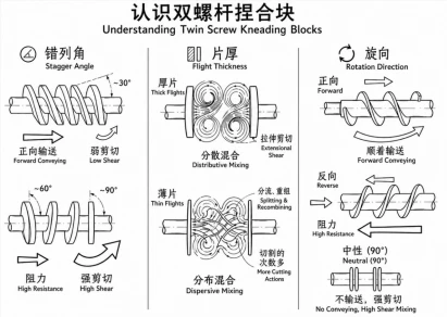
- Stagger Angle (Offset Angle): Common angles include 30°, 45°, 60°, and 90°. A smaller angle (e.g., 30°) maintains strong forward conveying and low pressure drop. As the angle increases toward 90°, forward pumping decreases, melt resistance rises, and shear intensity peaks.
- Disc Thickness: Thick discs generate strong extensional shear across the flight crests, favoring dispersive mixing (breaking down agglomerates). Thin discs split melt streams frequently, favoring distributive mixing (spatial homogenization).
- Flight Direction (Helix Orientation):
- Forward (Right-handed): Pumps melt forward under positive pressure.
- Neutral (90°): Provides zero axial pumping; relies entirely on upstream pressure.
- Reverse (Left-handed): Actively pushes melt backward, creating a high-pressure filled zone.
5 Classic Kneading Block Configurations (Weak to Strong Shear)
1. Pure Forward Small-Angle Configuration (Ultra-Weak Shear / Melting Transition
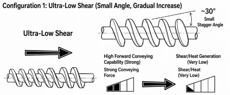
- Typical Layout: Forward KB 45° / 5 Discs (continuous sequence)
- Mechanics: With a 45° stagger angle, this setup maintains high axial pumping capability. Melt pressure remains low, and residence time is minimal.
- Primary Application: Early melting transition zones or heat-sensitive polymers.
- When to Use: Ideal for processing ultra-high-molecular-weight polymers, shear-sensitive bio-plastics (like PLA), or heat-sensitive additives. It provides smooth thermal transfer to turn solids into a semi-molten state without generating localized frictional overheating.
2. Forward Graduated Configuration (Moderate-Weak Shear / Standard Melting Zone)
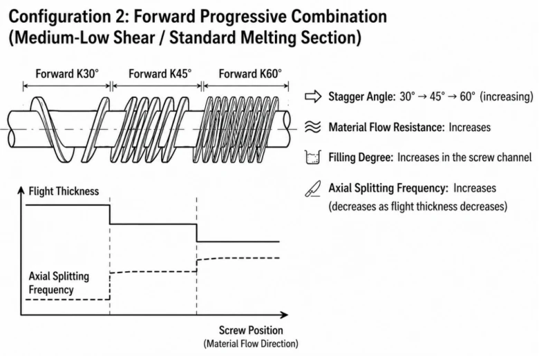
- Typical Layout: Forward KB 30° → Forward KB 45° → Forward KB 60° (Thick to Thin Discs)
- Mechanics: Increasing the stagger angle progressively increases flow resistance and barrel fill level. Transitioning from thick to thin discs increases axial stream-splitting frequency.
- Primary Application: Primary melting zone for general engineering plastics.
- When to Use: Standard compounding process setups for commodity resins such as PP, PE, and ABS. The gradual shear build-up prevents abrupt torque spikes and protects the resin from thermal degradation.
3. Neutral Block Combination (Moderate-Strong Shear / Classic Dispersion)

Typical Layout: Forward KB 45° → Forward KB 60° → Neutral KB 90°
Mechanics: The 90° neutral kneading block has zero axial pumping effect. Polymer melt must completely fill the screw channels upstream before forcing its way past the neutral block, inducing high radial shear and elongational flow.
Primary Application: Filler incorporation and general dispersion.
When to Use: Highly effective for dispersing inorganic fillers like calcium carbonate (CaCO3), talc, and titanium dioxide (TiO2). Forward blocks compress the melt, while the 90° element deagglomerates powder clusters.
4. Reverse Element Flow Restriction (Strong Shear / Deep Dispersion)
- Typical Layout: Forward KB 45°
 Forward KB 60°
  Reverse Conveying Element (or Reverse KB)
 - Mechanics: Placing a reverse element downstream forces material back against the forward flow, creating a 100% full, high-pressure melt seal (melt plug). Polymer must pass through narrow tip clearances under extreme dynamic pressure.
- Primary Application: Fiber degradation control, alloy blending, and fine dispersion.
- When to Use: Essential for glass fiber reinforcement (achieving optimal fiber length distribution) and polymer alloy compatibility (e.g., PC/ABS blends). Frictional heat generation is significant; screw speed and feed rate must be closely monitored.

5. Reverse Large-Angle Combination (Ultra-Strong Shear / Extreme Compounding)

- Typical Layout: Forward KB 45°
 Reverse KB 60° (or consecutive Reverse KB 45°)
 - Mechanics: Material is subjected to aggressive axial back-mixing, heavy surface scraping, and high Specific Mechanical Energy (SME) input.
- Primary Application: Nano-fillers and reactive extrusion.
- When to Use: Reserved for difficult-to-disperse nano-materials (e.g., carbon nanotubes, graphene) or chemical reactive extrusion processes (such as polymer grafting or controlled chain scission).
Kneading Block Configuration Summary Table
|
Configuration Type |
Stagger Angle & Layout |
Shear Level |
Primary Mixing Type |
Typical Application / Materials |
|
1. Ultra-Weak |
Forward KB 45° |
Ultra-Low |
Gentle Conveying / Heat Transfer |
Shear-sensitive resins, PLA, UHMWPE |
|
2. Graduated |
Forward 30° → 45° → 60° |
Moderate-Low |
Melting Transition |
Standard resin melting (PP, PE, ABS) |
|
3. Neutral Block |
Forward 45° → 60° → KB 90° |
Moderate-High |
Dispersive & Distributive |
Mineral fillers (CaCO3, Talc, TiO2) |
|
4. Reverse Restrictive |
Forward KB → Reverse Element |
High |
Intense Shear & Melt Seal |
Glass fiber chopping, PC/ABS alloys |
|
5. Reverse Large-Angle |
Forward KB → Reverse KB 60° |
Extreme |
High SME / Back-mixing |
Nano-compounding (Graphene, CNTs), Reactive Extrusion |
Practical Engineering Tips for Screw Design
To ensure optimal mixing performance and protect your machinery, follow these process engineering rules:
- Avoid Restrictive Elements Before Vent Zones: Never place a strong reverse kneading block immediately upstream of a vacuum degassing vent. Without a decompression zone, molten plastic will back up and flood the vent port.
- Follow a "Gradual-to-Focused" Intensity Profile: Build shear intensity progressively from the feed section to the compounding zone. Prolonged high-shear zones increase melt temperature uncontrollably and risk thermal degradation.
- Match Configuration to Melt Viscosity: High-viscosity polymers (like PC) require wider disc spacing and lower stagger angles to avoid torque overload alarms. Low-viscosity resins require tighter restrictions to achieve adequate filled-channel shear.
Elevate Your Compounding Process with JWELL Technology
Mastering screw configuration requires balancing flow behavior, melt viscosity, residence time, and mechanical energy. At JWELL, our advanced JWELL Twin Screw Extruder series is engineered with modular screw shafts and wear-resistant barrel components to meet demanding polymer compounding needs.
Whether you are processing high-filler masterbatches, engineering plastics, or bio-degradable compounds, JWELL's extrusion technology specialists can tailor custom screw geometries for your production line.